
Instruments: before, big and busy. After, uncluttered and simple.
There is a big difference between advice and opinion. One serves to guide and promote discourse, and the other invariably confuses things and promotes argument. I learned the difference between the two a long time ago and am constantly reminded of that lesson. When seeking advice we are generally hoping to tap into the accumulated knowledge and experience of others whose judgement we trust. Opinion on the other hand is generally something that follows acting upon advice and is subjective, unless of course, the other person has misconstrued your original query, in which case you get a whole load of one when you wanted the other. When I’m engaged in making stuff I ask for advice, when I need it, from other makers I know, and I might canvas their opinion when I’ve finished what I’m doing, but not before.
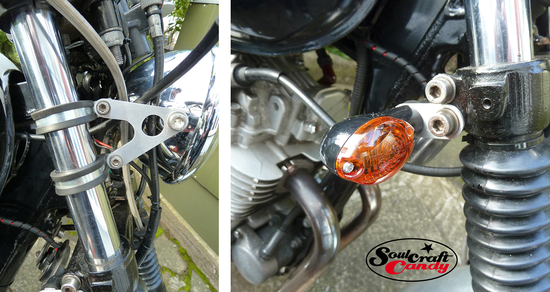
New headlight brackets and new front indicator light mounts.
If I’d followed all of the unsolicited “advice” I’d been given about how my bike should be, then I would have wasted a great deal of money and time on what is essentially a cheap form of transport. Working within an admittedly self imposed tight budget, and with time pressure to match, the solutions that interest me are those which are simple, relatively easy to execute and fit for purpose. It is with this in mind that I approach everything I do on this build and it helps to steer things clear of needless expense and wasted effort. One day I might build something more special but, for now I’ll work with what I’ve got. Sorting out the instrument area and the headlight would have been “better” if I’d totally stripped the bike of all electrics, cable drives and other bits, but that doesn’t clear the deck, it just opens up a whole new avenue of expensive solutions to a new set of problems. Working with what’s there meant splitting the clocks to allow cable drives to flex more freely and shorter light mounts to keep things close in and fairly tidy. The bundle of wiring needed to keep things working would stay, although shortened and repackaged. I’d bought some ‘P’ clips some time ago thinking they’d do for mounting the light on the forks and so put them to use. they work well enough for now though I may make replacements with a tighter fit later on. I drew up some side brackets on some graph paper (brilliant for laying out simple parts to scale) and transferred the design onto some aluminium alloy for cutting out. I made a new speedo mount based on what had been there before, but with a 20 degree offset and modified the mounting that came with the tachometer when I bought it, to bring it closer to the handlebar. All this allowed me to raise the light and split the clocks, and try to keep things as low as possible. By tilting the bars back further I was getting near to where I wanted the front to be. It looks a lot more sparse than before, but I’ll get used to it. And the natty little fly screen has gone.
I was very fond of it, but it had to go. A quick word about making those side brackets. Because I’d drawn them out on graph paper, it was easy to draw them again on alloy sheet, you remember all the numbers. I cut them out using a jigsaw, slowly, with a blade for metals at slow speed. I finished them off with hand files and drilled the holes with a hand drill. It takes time but not as long as you’d think and the result is pretty tidy once they’ve had a rub down with 600 grade wet and dry paper.
Here’s a canny bit of advice given to me by my father just before I started this: when filing soft metals, rub chalk along your files, it stops them from clogging. He was right, it did too. You can’t beat good advice. His opinion? Well, he didn’t have one, he’s waiting until I’ve finished to give me that.


