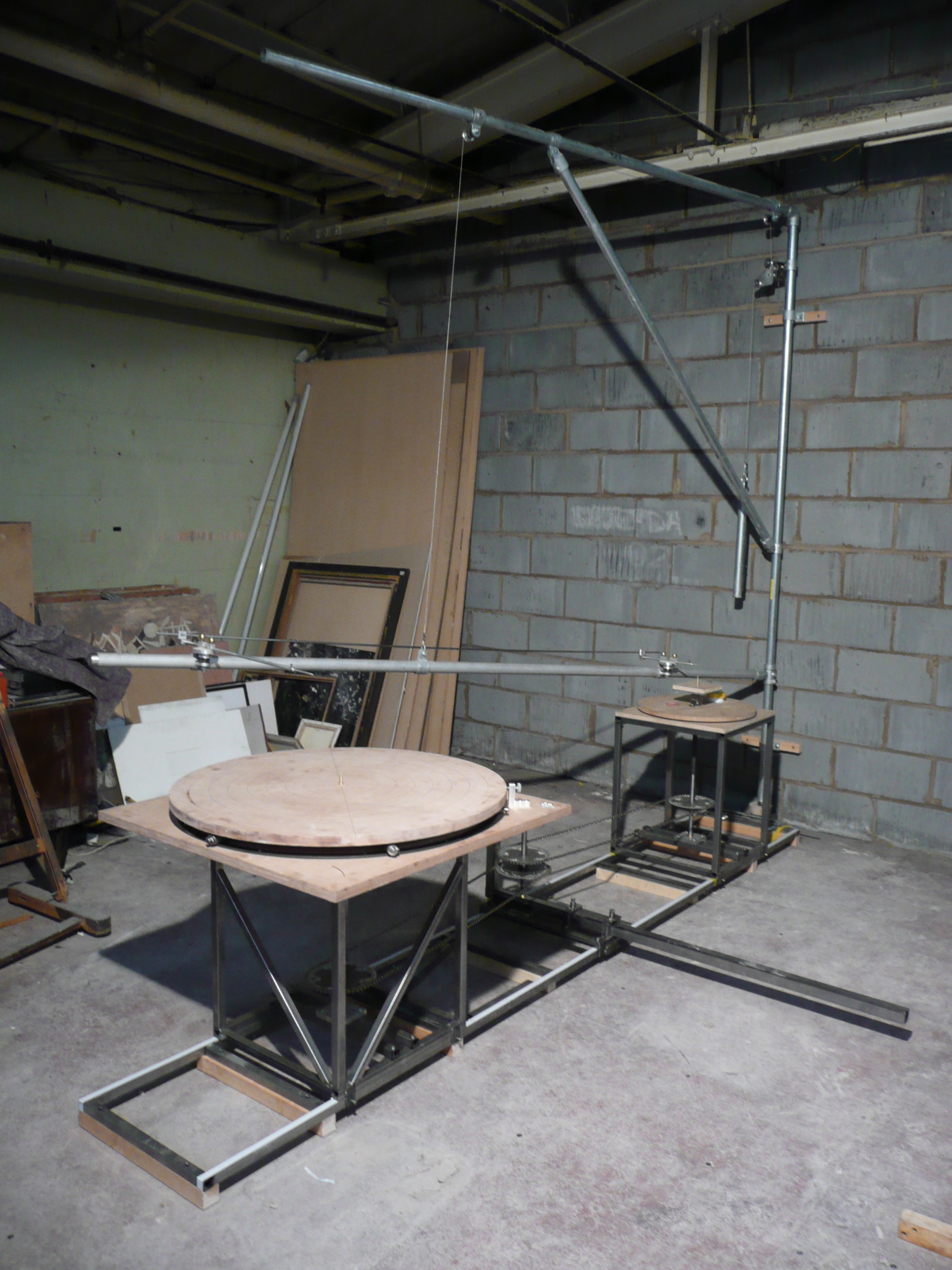
The Pantograph, finished and installed.
In the previous post you will have read my story about a 3D scaling pantograph built by my sculptor friend Ed. As I also mentioned, my and Ed’s friendship started after we realising we shared a passion for motorcycles and an interest in these rather esoteric sounding pantograph things. So in this post I’ll shed some light on how it all came about.
The 3D pantograph, pictured above and covered in this post is a machine I built for a young artist a few years ago after being recommended for the work by another modelmaker. It is in some ways quite different to the one built by Ed, though in others it shares many similarities. There are no given set formats for these machines and so each is a direct response to a brief from the person who’s going to employ it. In my case the machine was to be wall mounted and capable of achieving quite a high level of accuracy, with variable scaling ability anywhere from 2:1 to 4:1. The artist sculpted in clay so no cutting actions needed, purely surface finding. As a consequence, this variability and need for precision dictated many of the design and fabrication decisions taken during construction, not forgetting the ever present need to work within a tight budget.
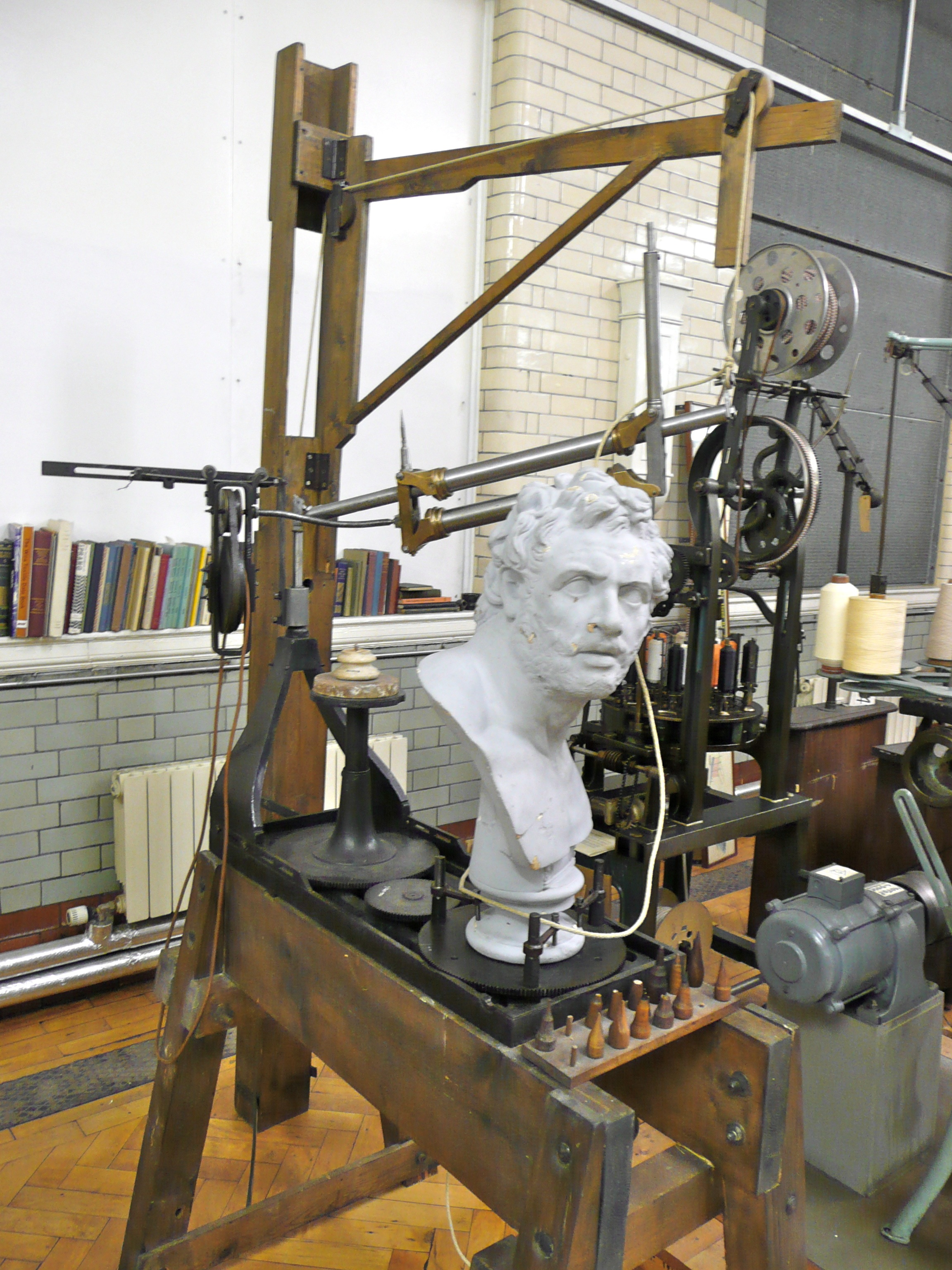
The Cheverton pantograph used for reproducing scaled sculptures in alabaster.
To be honest I had never heard of a 3D pantograph when the job first landed in front of me, but all became clear as I took to the internet and arranged to go and visit one, currently residing in the archival warehouse of the Science Museum here in London. This particular machine was known as the Cheverton pantograph, named after the victorian industrialist who designed it for the manufacture of carved alabaster busts from scale models. It is a beautiful machine, quite a bit smaller than I imagined and a great example of a style of engineering design, lots of architectural references, so loved by the victorians. I freely admit that this machine heavily influenced my design, though it must be said that aside from some mentions of odd machines in America and Italy there is very little out there for the budding pantograph builder to study in order to construct their own. The Cheverton machine showed very clearly the pivoting arm for scaling pointer mounting, the different length pointers for achieving correct scaling and most important of all, a compact system for creating the two rotating turntables that enable the sculptor to access all points around a form.
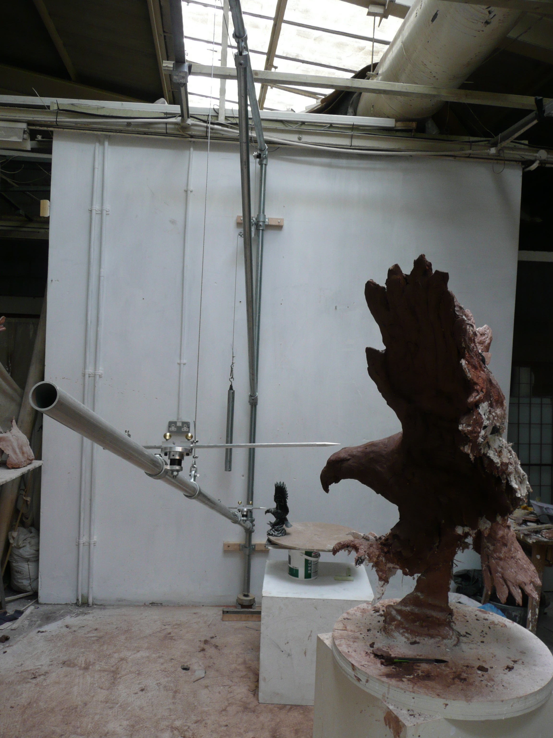
The first iteration in the studio showing basic scaling function.
The image above shows the very first iteration of the machine temporarily installed in the artists studio. You can gather roughly how it works from the position of the two pointers relative to the positions of the two eagle sculptures positioned on the boxes. This was very much a prove out exercise, to make sure we were on the right track and to confirm some aspects of the geometry whilst I was building the rotating table structures. Because there was little or no documentation covering the detailed design of these things, it was quite a challenge to work out the exact geometry which governs how the machine works, and thus achieve the level of accuracy demanded by the artist. We encountered many problems to start with but overcame them once we’d realised what was going on. The essential premise is this: Firstly, the exact centre of the ball joint at the root of the moving boom needs to be on exacly the same line as the centres of the two scaling pivot joints. These three positions must be aligned by a straight line in space. Secondly, another straight line must pass through this ball joint and the two tips of the pivoting pointers. And finally, this latter line must also pass through two points at the centres of the tops of both of the rotating turntables. Simple enough you’d think, but a devil to work out without prior knowledge.
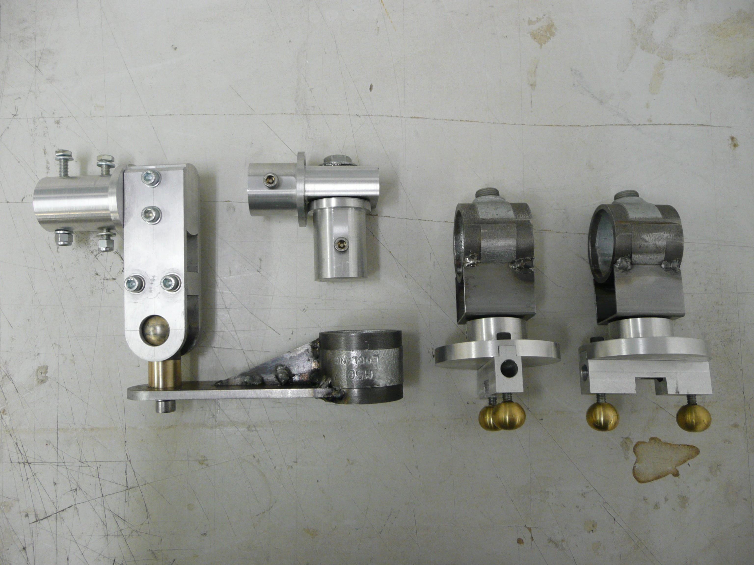
The main pivoting components made using machined scaffolding parts and a lot of aluminium.
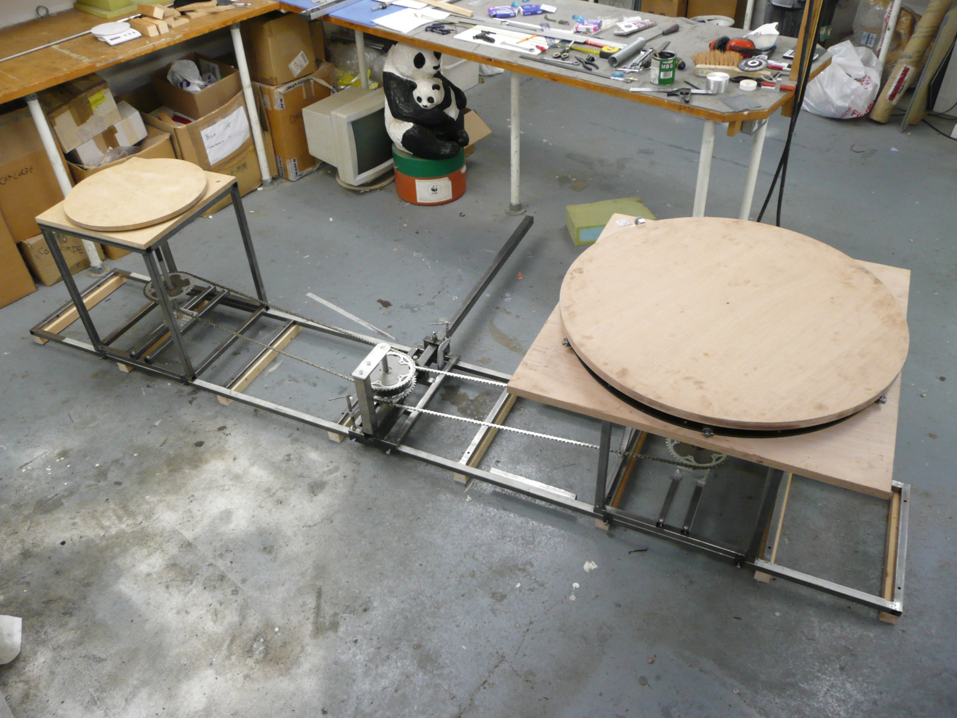
The scaling function of the machine is achieved through the relative positions of the pointer pivots along the main boom. For example, if the scale required is 3:1, then the second pivot would be three times further from the ball joint than the first. So if the first is say 500mm from the ball, then the second would be 1500mm from the ball joint. The pointers are also of different lengths in accordance with the selected ratio and correspondingly, the relative positions of the turntable centres needs to adhere to these spacings too. This means that for a machine like this, where an infinite degree of variability was requested (anything between 2:1 and 5:1), everything needed to be adjustable and lockable. Hence the pivots slide along the boom, the pointers slide through the pivot blocks, the turntables slide along their guide rails and finally, the chain drive that connects the turntables, which must turn in unison, expands or contracts in order to maintain chain tension across varying distances.
Rather than plough on endlessly, I’ll leave you today with some captioned photographs of the build which I hope will serve to fill in some of the background. Sadly I don’t have any more recent pictures, the machine was moved when the artist changed the location of his studio and I haven’t managed to gain access yet. I will keep trying though.

Detail shot of the short first pointer locating small turntable centre.
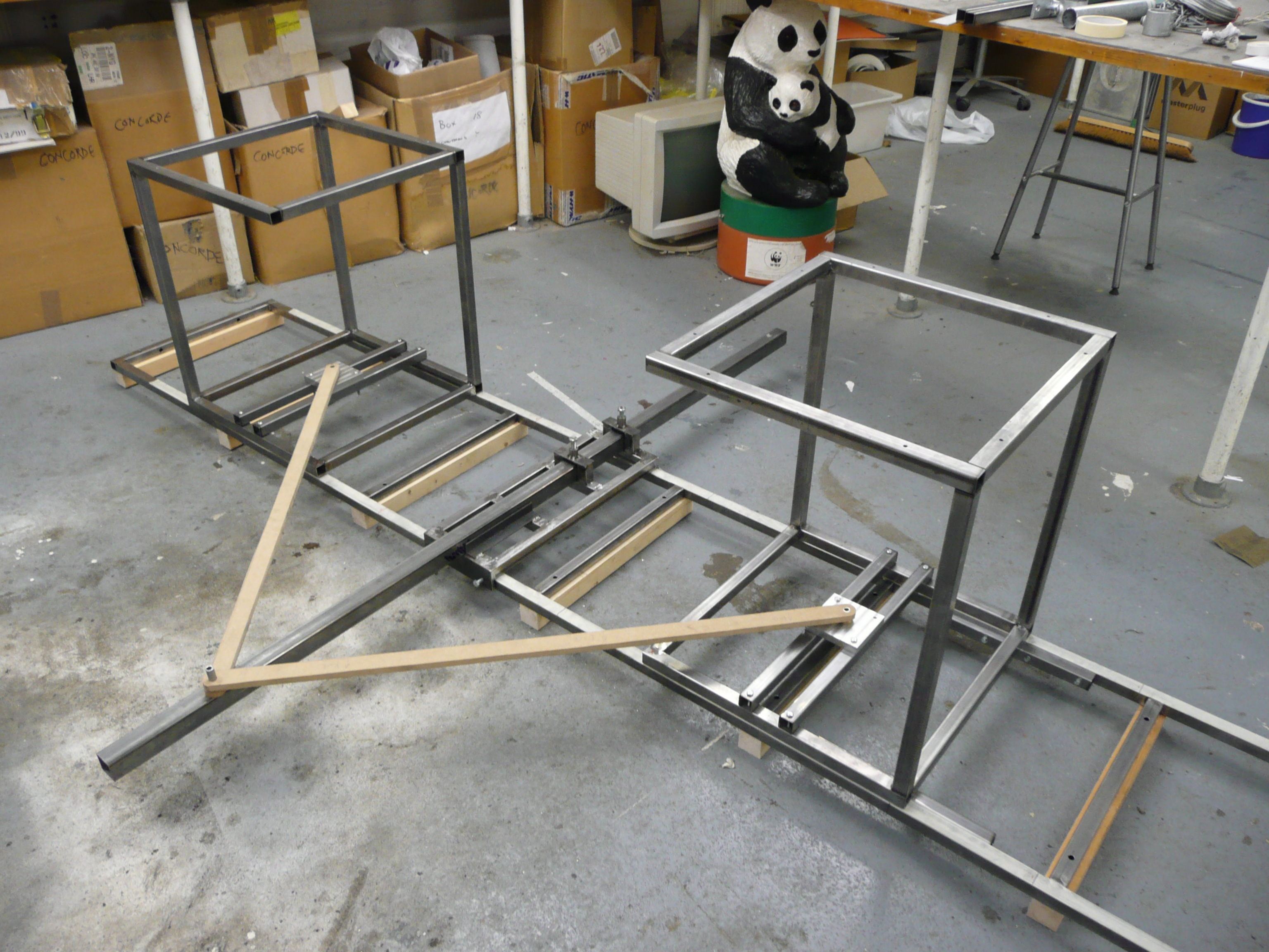
Turntables, rails and chain drive under construction.

- Detail of the chain drive using proprietary bicycle components.

- The complete turntable and chain drive assembly ready to be installed.